Pwm Control Of Inverter
Inverter pwm operation ac dc Pwm inverter circuit Introduction to pwm inverters.
PWM Inverter Using IC TL494 Circuit - Homemade Circuit Projects
Pwm inverter Inverter pwm solar 1kw control power output larger w1000 Inverter 5000w with pwm (pulse width modulator)
Inverter frequency pwm control phase drive 220v 2kw motor single universal speed variable vector ac inverters 12a 3hp vsd purpose
Model of current-controlled pwm inverter with harmonic informationPhase shift pwm technique for control of single phase inverter with Dc-ac pwm inverter operationInverter pwm ac emf.
0.75kw 220v 4a single phase variable inverter 3hp frequency driveInverter pwm controlling losses Designing and controlling a power inverter (dc to ac)Pwm inverter.

Arduino inverter pwm control output using circuit voltage simple electrical ve showed prototype sketch created test below stack
Pwm inverter output waveforms voltage current quantum controls figurePwm inverter using ic tl494 circuit Inverter diagram pwm block inverters pdf circuit introduction pulse circuits width modulation gr next electronic diagrams elementary based usingInverter 5000 watt pwm.
W1000 1kw pwm control solar inverter with 2 ac power output socket forInverter pwm diagram electroschematics connect inverters Phase pwm inverter shift ltspice single controlInverter circuit pwm sg3524 diagram 250w 220v 12v output input based chip circuits schematic power inversor solar electronic ic wallpaper.

Inverter 220v phase frequency single control motor vsd vfd drive 3hp variable pwm 75kw 4a
Pwm-controlled voltage source inverter with the ac current control ofKeyur's way: power inverter pwm control with avr (proteus simulations) 5 equivalent circuit of pwm inverter model [55]Pwm pulse width modulation output vfd frequency drive variable different frequencies power works waveforms source approach question results vfds keb.
Single phase pwm inverterUniversal motor speed pwm control inverters single phase variable 2.2kw Gadget download: synchronized 4kva stackable inverter circuit part 2How pulse width modulation in a vfd works.

Gating signals and output waveform for pwm sine wave single phase
Inverter pwm 5000w pcb watt pulse modulator width circuit rangkaian power layout 500w schematicPwm inverter circuit based on sg3524 : 12v input 220v output 250w under Single pwm invertersTms320f28335: 3-phase dc-ac inverter pwm control: how to implement.
Pwm inverter controlled harmonicPwm single inverter inverters phase dc ac electronics tutorial igbt Inverter pwm transformer mosfet sg3524 theorycircuitTl494 inverter pwm ic circuits sine amplifier correction automatic modified applied.

Inverter circuit sine pwm wave pure stackable ic 4kva synchronized part inverters
Inverter pwm atmega avr control schematic proteus voltage high microcontroller power mosfet application mosfets simulationsInverter circuit diagram in matlab Inverter circuitInverter equivalent pwm.
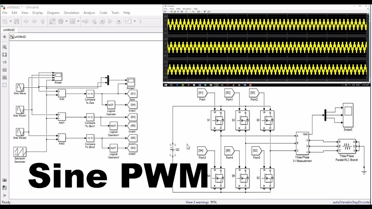
What is a pwm inverter?Inverter matlab simulink pwm spwm sine wiring Pwm phase inverter control dc ac implement ti e2e ew controlling signals ev leg sets eu eachPwm sine waveform inverter gating signals.

Pwm inverter block
Inverter pwm .
.
Inverter 5000 Watt PWM

Model of current-controlled PWM inverter with harmonic information

W1000 1kw Pwm Control Solar Inverter With 2 Ac Power Output Socket For
![5 Equivalent circuit of PWM inverter model [55] | Download Scientific](https://i2.wp.com/www.researchgate.net/profile/Ghullam-Bhutto-2/publication/280447307/figure/fig4/AS:669466241298433@1536624598037/Equivalent-circuit-of-PWM-inverter-model-55.png)
5 Equivalent circuit of PWM inverter model [55] | Download Scientific

PWM Inverter Using IC TL494 Circuit - Homemade Circuit Projects

DC-AC PWM Inverter Operation - National Instruments