Pwm 555 Circuit Mosfet
555 circuit ic pwm inverter using astable sg3525 variable timer cycle duty circuits homemade power bistable modes explored pinouts monostable 555 pwm mosfet diagram Trouble activating a mosfet with a 555 pwm circuit
PWM 555 Timer MOSFET - Multisim Live
Schematic different why mosfets switching speed being than they driven circuitlab circuit created using Mosfet pwm electromagnet Pwm 555 motor circuit dc control power supply speed 90vdc circuits timer astable fan battery circuito mosfet velocidad diagrama circuitos
555 pwm circuit and using n mosfet to drive electromagnet coil(load
Pwm inverter circuitHow to use ic 555 for generating pwm outputs 555 pwm circuit and using n mosfet to drive electromagnet coil(loadPwm 555 timer mosfet.
Ic 555 pinouts, astable, monostable, bistable modes exploredMosfet pwm ne555 driving driver circuit schematic opening completly drivers english Mosfet application circuitsMotor irf540 mosfet dc control speed ne555 using pwm arduino.

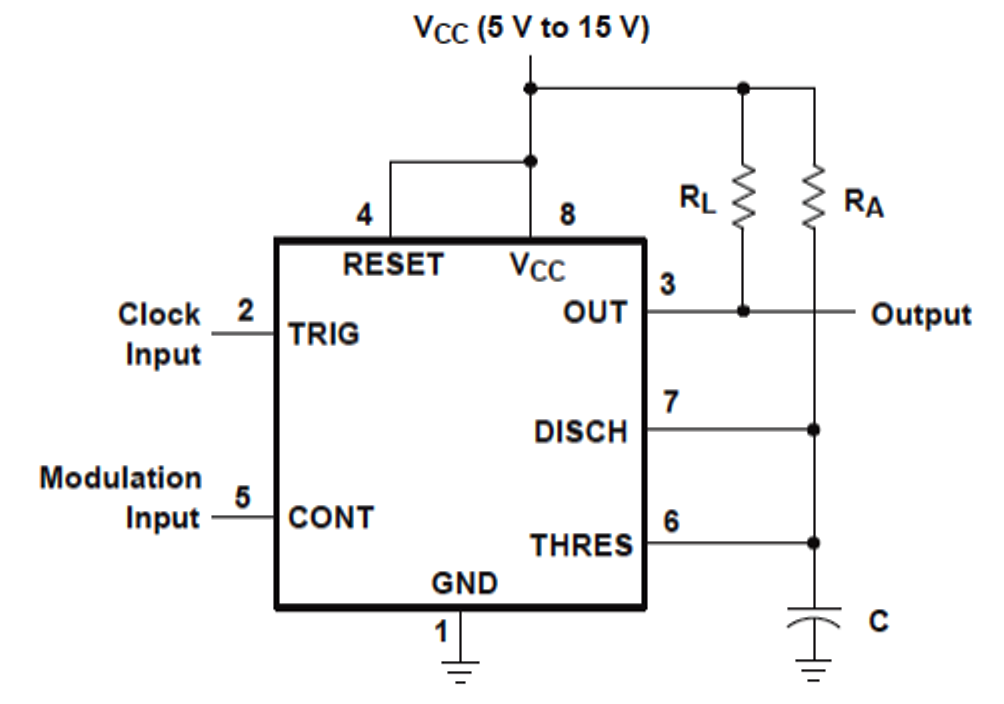
Pwm, pam, ppm using ic 555
High current pwm (1500w) with ne555 and irf3205 mosfetsDriving mosfet with 26khz pwm from ne555, mosfet not opening completly Circuit motor speed control 90vdc simple mosfet pm need help controller pwm obviously scaling amps handle bridge below soDc motor speed control using ne555 and irf540 » electroduino.
A low cost pwm dimmer using ne555 and mosfet with diy aluminium casePwm 555 circuit dimmer led mosfet light sparkfun ne555 timer 12v applications arduino using brightness circuits current potentiometer project high Inverter pwm circuit mosfet sg3524Using a pwm signal generator to drive mosfet transistor?.

Pwm 555 ppm using pam ic modulation pulse circuit width
Amplifier mosfet circuits schematics layout voltage 回路 pcb irf530Multisim pwm mosfet Inverter mosfet ne555 volts eleccircuit sine voltage schematics 50hz transformer amplifier inverters figure1Mosfet driver simple schematic circuit using switch 4a circuitlab created stack.
555 to drive a mosfet555 pwm diagram vape mosfet ttl mod box wiring diy used cmos standard open Pwm mosfet mod diagram stripboard fet buffered switches slide withoutMosfet circuit pwm drive driver using coil electromagnet load circuits gr next complementary stage try could between add.
555 pwm circuit ic diagram simple using generating use generate mode circuits configuration following learn let homemade outputs monostable pinout
Mosfet driver: popular, cheap, all-in-one for analog pwm?Pwm analog mosfet cheap modulators circuits linear Pwm ne555 mosfet dimmer instructables circuitsPwm mosfet generator transistor signal using drive circuit 100v assuming wanted use stack.
Pwm ne555 high current irf3205 mosfets 1500w555 pwm mosfet diagram Versatile 555 timer pwm controlMosfet pwm control timer motor.

Mosfet drive driver
Ic 555 inverter circuit using mosfetPwm circuit ltspice implementation Analysis of 555-based pwm circuit.
.


a low cost PWM dimmer using NE555 and MOSFET with DIY aluminium case

PWM, PAM, PPM using IC 555

Driving MOSFET with 26kHz PWM from NE555, MOSFET not opening completly

555 to drive a MOSFET - Electrical Engineering Stack Exchange

DC Motor Speed Control Using Ne555 and IRF540 » ElectroDuino

High Current PWM (1500W) with NE555 and IRF3205 MOSFETs - YouTube

design - Functional difference between various astable 555 circuits