Circuit Diagram Of Boost Converter
Boost converter basic circuit pwm electronics dc voltage high output control down converters timer directly comparator Boost converter Boost converter circuit schematic make electrical layout circuitlab created using stack
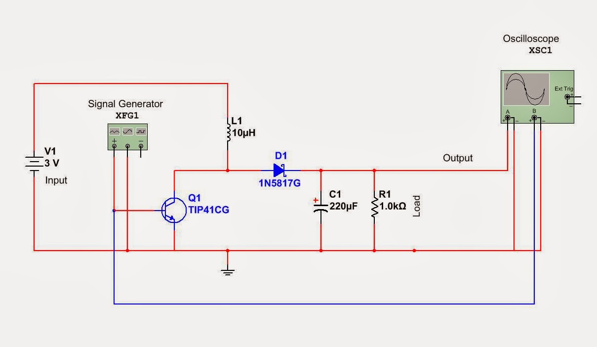
How to Build a DC-to-DC Boost Converter Circuit
Boost converter circuit converters work homemade voltage relay capacitor process results 555 boost converter circuit ic components timer using transistor capacitor bc547 npn required diode Boost converter circuit schematic kickback inductive charging simple gif prototype electric self car understanding viewed kb times
Circuit diagram of the boost converter.
How to build a dc-to-dc boost converter circuitDc to dc boost converter circuit (part 5/9) Dc to dc boost converter circuit homemadeConverter boost ir2110 microcontroller using pic circuit dc schematic microcontrollerslab diagram pwm voltage proteus current should mosfet.
Converter boosterBoost converter dc arduino circuit lm2577 feedback schematic diagram potentiometer electronoobs code Simple 3 amp. dc to dc boost converter circuit diagramPower supply.

Boost converter circuit
Dc to dc boost converter circuit (part 5/9)Converter boost circuit Converter circuit unidirectionalHow boost converters work.
Get torrents from my blog: buck boost converter circuitHow to make a boost converter circuit Circuit converter boost work voltage supply power1 circuit diagram of boost converter..

Diode capacitor schottky resistor inductor
10+ boost converter circuit diagramBoost converter schematic Simple boost converter circuit5v boost converter.
Boost buck circuit converter xl6009 diagram regulator using voltage adjustable 12v output switching 3v circuits shown belowBuck boost regulator circuit design using xl6009 with adjustable 3.3v Buck converter circuit boost voltage circuits power dc ac diagram supply gr next torrents batteryBoost converter circuit free download programs.

Boost eleccircuit 5v
10+ boost converter circuit diagramBoost converter circuit 555 Circuit diagram of boost converterBoost converter circuit 5v using diagram.
Circuit converter boost dc diagram partI like free ware files: boost converter schematic Boost converter using ir2110 and pic microcontrollerBoost converter diagram dc simple circuit topology conduction converters voltage mode output discontinuous analysis schematic engineering equilibrium low four current.

Ideal unidirectional dc-dc boost converter circuit
Circuit diagram of boost converterCircuit dc converter boost build inductor shown below breadboard above pdf Boost converter circuit using mc34063 icKl03 control pwm output directly with comparator.
.


Circuit diagram of boost converter | Download Scientific Diagram

1 Circuit diagram of Boost converter. | Download Scientific Diagram

How to Build a DC-to-DC Boost Converter Circuit
Boost Converter Circuit free download programs - morehelper

Simple 3 Amp. Dc To Dc Boost Converter Circuit Diagram

microcontroller - Boost converter help - Electrical Engineering Stack

DC to DC Boost Converter Circuit (Part 5/9)