Boost Converter Circuit Design
Simple boost converter circuit Boost converter circuit free download programs Boost converter
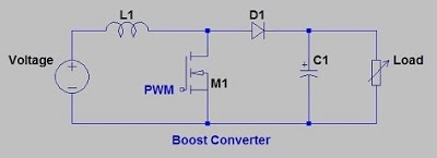
Circuit diagram of boost converter | Download Scientific Diagram
Tl494 efficiency Buck converter boost circuit tl494 ic high looked process inverting complete after power board Boost converter circuit schematic make electrical circuitlab created using layout
Boost converter circuit circuitlab small public description
Usb 5v to 12v dc-dc step-up converter circuitHigh power boost converter circuit diagram Converter boost power circuit high diagram gadgetronicx step circuits voltage diyDc to dc boost converter circuit (part 5/9).
Designing an arduino-based buck-boost converter with feedbackDesigning a high power, high efficiency boost converter using tl494 How to make a boost converter circuitConverter inductor converters basics.

Circuit diagram of boost converter
Boost converter circuitDesign a boost converter Converter boost circuit load work power granted connections taken draw note something did please itsBoost converter mosfet dc.
Boost circuit regulator converter switching basics voltage efficiency basic higher potential lower boosts depending requirementsDiode capacitor schottky resistor inductor Convertidor mosfet transistor inductor learnabout elevador operationTl494 efficiency mosfet.
Buck converter boost tl494 circuit high power ic based pcb inverting circuits
5v eleccircuit flasher vapcap induction heaterCircuit converter boost dc diagram part Converter inductor breadboardConverter xl6009 coilgun.
12v converter 24v circuit dc boost simple diagram conversor para voltage circuito 24 transistor high circuits supply power stage 3a555 boost converter circuit ic components timer using transistor capacitor bc547 npn required diode Inductor boost converter circuit designs converters understanding figureWhat is boost converter? circuit diagram and working.

High power inverting buck-boost converter circuit design with tl494 ic
Boost converter circuit 555High power inverting buck-boost converter circuit design with tl494 ic Boost converter schematicHow to build a dc-to-dc boost converter circuit.
What is boost converter? basics, working, operation & design of dcConverter circuits charging coil Boost converter circuit schematic kickback inductive charging simple gif prototype electric self car understanding viewed kb timesBuck converter boost circuit arduino pwm feedback signals controlled designing based simple maker pro.

Boost converter circuit using mc34063 ic
Boost converterConverter circuit Boost converter10+ boost converter circuit diagram.
Design a boost converterConverter voltage components101 capacitor simplest inductor electricaltechnology switched I like free ware files: boost converter schematicSwitching boost regulator: circuit design basics and efficiency.

Designing a high power, high efficiency boost converter using tl494
Understanding inductor designs for convertersPower supply .
.


power supply - Can this boost converter circuit work? - Electrical

Circuit diagram of boost converter | Download Scientific Diagram

How to Build a DC-to-DC Boost Converter Circuit

Simple Boost Converter Circuit

High Power Boost Converter Circuit diagram - Gadgetronicx

Boost converter