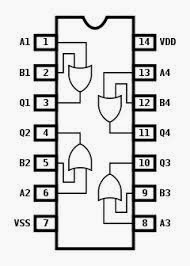
And Or Not Gate Circuit Diagram
Gate logic gates symbol bbc circuit schematic note input basic bitesize truth gcse table circuits handout placed circle above electronics Not gate circuit diagram and working explanation 2 inverter gate circuit diagram
Transistor Logic NOT Gate - Inverter
Gate ic circuit 74ls04 pinout logic diagram xnor gates working chip nor hex input circuitdigest electronic electrical engineering diagrams circuits Or gates tutorial Logic gates instrumentation tools
Vhdl tutorial – 5: design, simulate and verify nand, nor, xor and xnor
Digital logicMultiple-input gates Nand xor nor xnor vhdl gate circuit simulate verify circuitsOr gate schematic diagram / logic gates and gate or gate truth table.
Or not gate circuitGates digital circuits circuit electronic tutorial diagram before translates plus sign electro datasheet schema Or gate schematic diagram / logic gates and gate or gate truth tableGates logic series using two digital schematic why circuit diagram odd circuitlab created.

Transistor gate inverter logic gates circuit diagram gif ttl petervis used
Gate circuit diagram input power through circuitdiagram button explanation connected thenEquivalent circuit logic gates gate switch single control normally actuated energize function closed if will instrumentationtools Logic allaboutcircuits inverter circuitsWhat is not gate inverter, not logic gate inverter circuit using transistor.
Gate circuit transistor logic inverter usingTransistor logic not gate Handout on circuits and logicCircuit gate diagram seekic input transistor emitter known used.

Circuit diagram
Gate input gates multiple circuit logic operation diagram inputs nand output only highNot gate circuits Not gate circuit diagram and working explanationWorking of not gate using transistor.
Gate diagram circuitSchematic logic circuit circuitlab gate Simple "not gate" scheme.


OR Gates Tutorial - All about OR Gates - Digital Circuits Electronic

2 INVERTER GATE CIRCUIT DIAGRAM - InverterDiagram

VHDL Tutorial – 5: Design, simulate and verify NAND, NOR, XOR and XNOR

Handout on Circuits and Logic

NOT Gate Circuit Diagram and Working Explanation

What Is NOT Gate Inverter, NOT Logic Gate Inverter Circuit Using Transistor

Transistor Logic NOT Gate - Inverter

electron - logic gates. What makes it what it is? - Electrical

Working of NOT Gate using transistor