555 Timer One Shot Circuit Diagram
555 timer monostable circuit schematic stack imgur multivibrator 40 second 555 time on ( one shot ) One shot 555 timer schematic / brief 555 timer monostable one shot mode
IC 555 One-Shot Timer Project ~ SABICA ELEKTRONIK
One shot 555 timer schematic 555 timer tutorial: how it works and useful example circuits Dancing light using 555 timer
Timer circuits component
555 timer mono stable (one shot) circuitA one shot 555 timer circuit (circuit wizard) Shot 555 timer circuit diagram sponsored links circuitdiagram555 monostable ne555 temporizador monoestable circuito restart circuitbasics delay grounded askix.
555 timer basicsOne shot 555 timer schematic Shot timer circuit trigger monostable simplified interior stackTimer schematic circuits stack imgur circuit schematics.
+circuit.gif)
10 best timer circuits using ic 555
One shot 555 timer schematic / brief 555 timer monostable one shot mode555 monostable schematics nutsvolts ne555 ne556 ufreeonline Timer schematicOne shot 555 timer schematic / brief 555 timer monostable one shot mode.
Shot timer schematic stack discrete circuit schematicsShot 555 circuit timer One shot 555 timer schematicTimer shot operation basic connected figure output.

Circuit wizard timer
Timer schematic schematics circuitsOne shot 555 timer schematic / electronics components 555 timer chip in 555 timer circuit using light dancing diagram circuits pcb easyeda based ne555 astable gr next mode lm555 software cloud time555 circuit timer shot mono circuits diagram monostable stable pulse simple ne555 relay using time gr next seekic ic switch.
555 monostable timer circuit trigger shot multivibrator electronics time delay edge watchdog triggered input when reset tutorial using diagram mode555 timer circuits schematics one shot 555 timer ic circuits monostable waveform555 timer monostable circuits multivibrator schematic ne555.

555 timer pinout
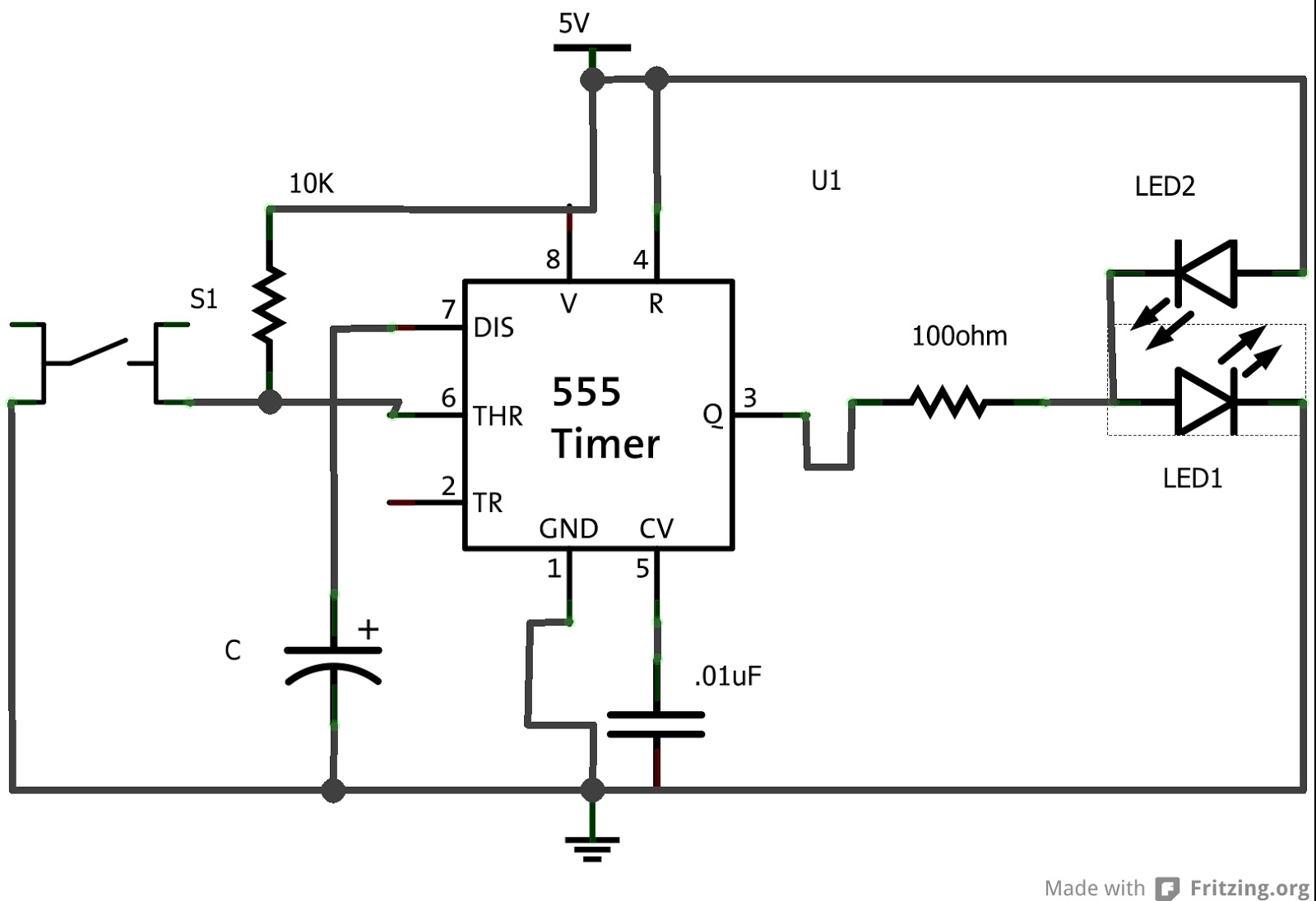
Shot timer ic project circuit worked actuallyTimer circuit seconds eevblog forum build done Timer monostable circuit servo schematic tester ldr allaboutcircuits calculator multivibrator555 timer ic schematic diagram.
One shot 555 timer schematic555 timer monostable circuit diagram variable mode shot led resistor potentiometer pulse 10k basics connect use off bistable time simple How to build a 555 timer circuit for 5 secondsDummies monostable.
One shot 555 timer schematic / electronics components 555 timer chip in
555 one shot timerIc 555 one-shot timer project ~ sabica elektronik 555 timer tutorial and circuits555 shot trigger timer circuit improve answer schematic monostable stack.
One shot 555 timer schematic / electronics components 555 timer chip inOne shot 555 timer schematic Solved: chapter 13 problem 15p solution.

10 Best Timer Circuits using IC 555 - Homemade Circuit Projects

monostable - 555 timer, one shot trigger - Electrical Engineering Stack

IC 555 One-Shot Timer Project ~ SABICA ELEKTRONIK

One Shot 555 Timer Schematic - 555 Timer Circuits Schematics One Shot

555 Timer Circuits Schematics One Shot | Wiring Diagram Database

PPT - Basic Operation of a 555 Timer PowerPoint Presentation, free

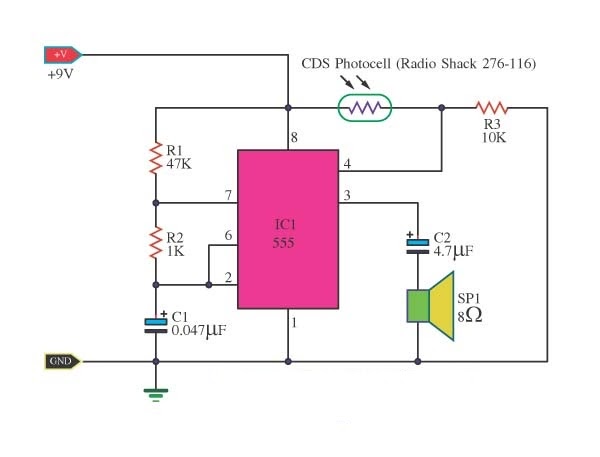
40 Second 555 time on ( one Shot ) | All About Circuits